Milestone: Phase 1
Initiation and Standards (The "Blueprint" Phase) = Recognizing Standard Operating Procedures (SOP) and learning the process. This prevents injury and insures success. Always remember this, "If you fail to plan, then you plan to fail." Make a plan and follow it.
Before a single line of code is written, you must define the environment and the "Rules of Engagement".
(A) Define the scope and Functional Specification: document exactly what the machine should do. If it's a pump station (for example), define flow rates, alarm setpoints, and fail-states.
(B) Establish SOP's and Coding Standards (Tag Naming Conventions): define how tags will be named. For example, Area_Equipment_Component_Function. AOI's (add on instructions) and user-defined data types (UDT's): create reusable blocks for motors, valves, and analog inputs to ensure consistency.
(C) Hardware Selection: finalize the AB or Siemens Controller and I/O modules based on the I/O count and communication requirements.
(D) Network Architecture: design the industrial network (ethernet I/P). Assign IP Addresses and define the physical topology (DLR - device level ring vs. Star).
Milestone: Phase 2
Execution and Development (The "Build" Phase) = This is where the logic and hardware configurations are created.
(A) Logic Development: create the ladder logic (LDR) in Studio 5000 or in Tia Portal (Version Varies). Use a modular approach (Program >>> Routine) to separate Auto, Manual Alarms, and Scaling Logic.
(B) HMI/Scada/Factory Talk View/Emulator/Simulator/etc.: Develop the visualization. Ensure all HMI tags map correctly to the PLC tags created in the previous step.
(C) Device Communication Setup: Configure the I/O tree in either Studio 5000 or in Tia Portal. Establish communications with VFD's (Powerflex, sew euro drives, encoders, or remote I/O via EDS files or AOP's (add-on profiles).
(D) Visual Testing (Emulation): Use Studio 5000 Emulate or Factory Talk Logix Echo, or etc.. Map physical inputs to "Toggle Tags" to simulate real-world feedback without needing the hardware.
Milestone: Phase 3
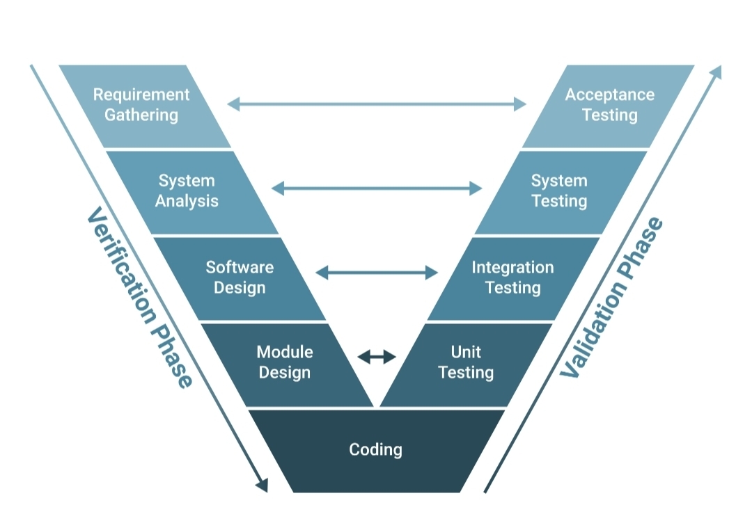
Validation and Simulation (The "Proof" Phase) = Before the PLC ever touches a live machine, it must be "vetted" through several layers of testing.
(A) Factory Acceptance Testing (FAT):
- I/O Simulation = use a simulation program to mimic field devices (example: if the PLC turns on an output, the simulation must "send back" a confirmation input within 2 seconds (timeframe varies based on coding).
- Conditional Scenarios: Test "What-if" scenarios:
- What happens if E-stop is pressed during mid-cycle?
- What happens if communications to a VFD is lost?
- What happens if the PLC losses power?
(B) Alarm Audit: Trigger every possible alarm to ensure the HMI displays the correct message and the PLC reacts safely.
(C) Interlock Verification: ensure safety interlocks cannot be bypassed by software or manual overrides.
Milestone: Phase 4
Installation and Commissioning (The "Go-Live" Phase) = the transition from the office to the factory floor.
- Physical I/O Checkout (point to point): verify that every wire landed on a terminal block actually triggers the correct bit in the PLC.
- "Dry Run" cycle the machine without product or high voltage. Check for motor rotation direction and sensor alignment.
- "Wet Test" or "Wet Run" / Process Tuning: run the system with actual product. This is where you perform PID loop tuning for valves or temperature controls.
- Site Acceptance Testing (SAT): final sign-off with the end user ensuring the system meets the original functional specification from Phase 1.
- As-Built Documentation: update the electrical schematics and PLC program with any "field changes" made during commissioning.
Critical Steps Often Missed:
- Change Management: implement a version control system (like FactoryTalk Asset Centre) so you can "Roll Back" if a live change breaks the system.
- Fault Recovery: Explicitly program how a machine "restarts" after an E-stop. Does it stay where it is, or does it need to go to a "home or "reset" position?
- Cybersecurity: ensure unused ethernet ports are disabled and the PLC "key switch" is moved to RUN MODE (not REMOTE MODE) once the project is finished to prevent unauthorized remote changes.